Three Row Roller Slewing Bearing
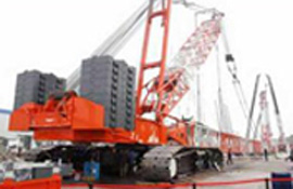
Among the various types of bearings used in the construction industry, the three row roller slewing bearing has a very high carrying capacity. This makes it the best choice for the use of heavy machinery. It is also ideal for the application where fatigue life and sub-surface cracking is a concern.
High carrying capacity
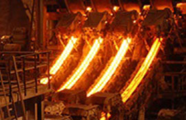
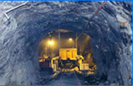
Using a three-row roller slewing bearing is an effective way to improve the carrying capacity of a machine. The slewing bearing provides 360deg slewing support for stackers and cranes. It is also used in heavy-duty machines with large working radii. It is widely used in mining machinery, construction equipment, and wind power equipment.
The most important characteristic of a slewing bearing is the load carrying capacity. This is determined by the maximum permissible pressure in the contact zone of the most loaded rolling element. Generally, this is derived from a single equation. However, the calculation method should take into account the rigidity of the screw connection and seats in the load-carrying structure.
A three-row roller slewing bearing has an extremely high carrying capacity. This is because the upper and lower rows of rollers are arranged horizontally and vertically, respectively. The lower row has a radial force while the upper row bears an axial force in two directions.
Finite element stress distribution model
FEA is a familiar modeling method and a great way to investigate complex nonlinear behavior. In this paper, a finite element stress distribution model for three row roller slewing bearing is evaluated and validated. This approach may be applied to other types of bearings, such as tapered rollers and ball bearings.
The first step in the process is to define a finite element model that will accurately represent the slewing bearing's geometry. For this task, ANSYS Workench 12.1 is used as the FEA tool. Similarly, a reference bearing is modeled to estimate its radial stiffness.
The aforementioned model is improved by adding a diametral clearance. This is in keeping with the structural deformation of the bearing rings. The result is a more accurate FE model. Afterwards, the aforementioned model is verified using contact pressure sensors. The results indicate that the proposed approach is a more realistic approach to modeling the slewing bearing.
A mixed finite element model is utilized in conjunction with the aforementioned approach to provide an improved calculation method. This model takes advantage of the fact that a symmetrical system can have one or two symmetry planes. It also allows for an improved estimation of the reasonable dimensions of the individual elements.
Suitable for heavy machinery
Generally, three row roller slewing bearings are used for heavy duty machines with large working radius. They distribute the load to different rows of the raceway. This allows them to bear multiple loads at the same time.
This type of slewing bearing is also used in the construction sector and public works. Depending on the application, other requirements must be considered. These include accuracy, rotational speed, and friction resistance. Other factors, such as the temperature range of the operating environment, may also have an impact on the choice of slewing bearing.
There are four main types of slewing bearings: single row, four point contact ball, triple row, and cross roller. Each is designed to handle a different combination of axial and radial force.
In the case of a single row four point contact ball slewing bearing, a row of steel balls are rolled along a raceway. This is followed by the change of contact from point to line.
Fatigue life and sub-surface cracking
Various types of rolling bearings are subjected to fatigue life and sub-surface cracking. The most common type is the three row roller slewing bearing. It contains three cylindrical rollers in the inner ring and an outer ring with a cylindrical roller. The rollers are arranged on a vertical raceway. The contact angle is 45 deg. The nominal load is p = ten times the rolling element's Young's moduli of elasticity.
The first indication of fatigue failure is sub-surface fatigue. This is generally five to six microns deep. It is caused by the alternating subsurface shear stress. It results in the propagation of small cracks, which can eventually lead to the fracture of the rolling element.
Some researchers have developed mathematical models for assessing the lifetime of the contact in rolling bearings. These models use statistical methods to estimate the fatigue life of the contact and the contact stress. In addition, these models are based on the Hertzian contact theory. However, they are not suitable for all slewing bearings.
- Previous: How to Find a Reputable Manufacturer of Slewing Bearings
- Next: How to Choose the Right Slewing Gear Bearing
Products
- Thin-Section Bearings
- Cylindrical Roller Bearings
- Tapered Roller Bearings
- Slewing Bearings
- Ball Bearings
- Precision Angular Contact Ball Bearing
- Precision Angular Contact Bearing 70 Series
- Ultra High Speed Angular Contact Bearing With Seal H70 Series
- High Speed Angular Contact Ball Bearing Sealed H72 Series
- Screw Bearing With Sealing
- Super High Speed Angular Contact Bearing B70 Series
- Sealed Ultra-high Speed Angular Contact Bearing SH70 Series
- High Precision Angular Contact Ball Bearings 72 Series
- Ultra-High Speed Angular Contact Bearings With Sealing B719 Series
- Crossed Cylindrical Roller Bearings
- Crossed Tapered Roller Bearings
- Spindle Bearings
- Thrust Roller Bearings
- Thrust Ball Bearings
- Spherical Roller Bearings
- Spiral Roller Bearing
Our company can produce more than 3000 kinds of standard and nonstandard rolling bearings in 9 different categories. Our company products are commonly used in metallurgy, mining, machinery, petroleum industry, electricity etc.